ISO/DIM - Isolation Transformer & Dim Bulb Tester
An isolation transformer is wired in between mains power and your DUT. The air gap in the transformer provides physical and electrical isolation between the mains earth ground and the DUT. Perhaps the most well-known example of their use is when an oscilloscope is to be connected to the DUT. The barrel of the BNC connector (and the thus the probe alligator clip) on nearly all oscilloscopes is referenced to mains earth ground. If your DUT is not isolated, it then becomes possible to short its positive voltage rail to mains earth ground either by connecting the alligator clip directly, or accidentally brushing a positive voltage contact. The result can be catastrophic — an exploding probe, damaged equipment, and electrocution. For more on this see these excellent, informative videos.
EEVBlog - How NOT To Blow Up Your Oscilloscope
Uncle Doug - Isolation Transformers: Internal Design and Safe Use with Oscilloscopes
ISO/DIM Schematic
The schematic above (created with Inkscape) shows the internal wiring of the ISO/DIM. Mains power comes in on the lefthand side and is provided to the rest of the unit through an Input Power DPST switch. Next is the isolation transformer wired in parallel to provide a 1:1 VAC output. A 5A circuit breaker (CB) is wired off the output Line side of the transformer. This CB may have been more useful wired on the input side, but in emails with the vendor, I learned that the worst-case surge current can approach 500A! While this would only be present for a matter of milliseconds, maybe not long enough to trip the CB, I wanted to avoid that possibility entirely. Better to place the CB on the output side which avoids this transient surge current running through it and still protects the input section of the unit.
Next is the Limit/Bypass DPDT switch. In the Limit position, current is directed through the dim bulb, and the Limit LED illuminates. In the Bypass position, the dim bulb is switched out of the circuit, allowing full current to the output section, with the Bypass LED illuminating. A voltmeter is hung off the common pole(s) of this switch, providing a mains VAC reading. The Output Power DPST switch enables or disables power to the DUT outlet (whose earth ground pin is not connected), with the PWR OUT LED providing visual indication that output power is enabled. Finally, an ammeter is connected in-line, displaying the current drawn by the connected DUT.
Bill of Materials
Chassis -- Tysun Silver Aluminum Electronic Enclosure Project Box
I used their free software to design the front panel and Front Panel Express did the cutting and etching, all at a reasonable cost. Highly recommend their services.
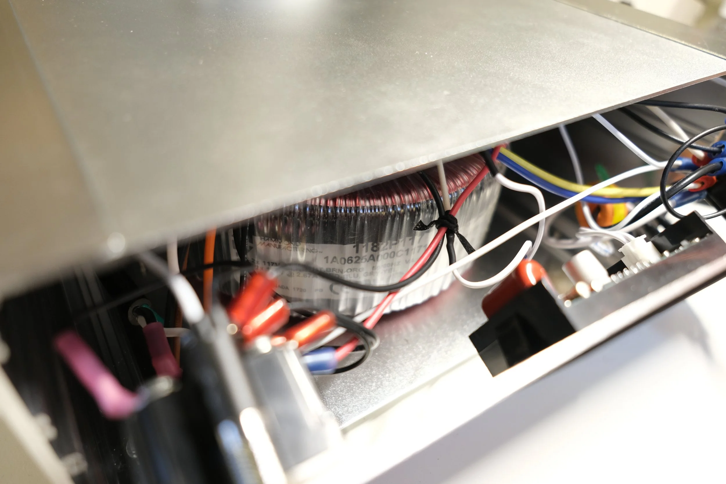
Toroid Power Transformer — Hammond Manufacturing PN: 1181P117
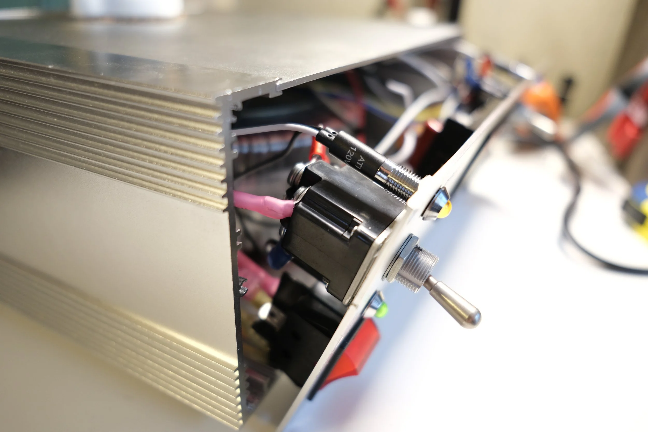
Input Power Switch — DPST Red Light Illuminated Boat Rocker Switch
Limit/Bypass, Output Power switches - DPDT 15A/125V Switch
These high quality MIL SPEC switches are not inexpensive; I routinely call them out at work and they’ve always performed well. Datasheet (PDF)
Limit, Bypass, and PWR OUT LED — Alpinetech 8mm 120VAC LED
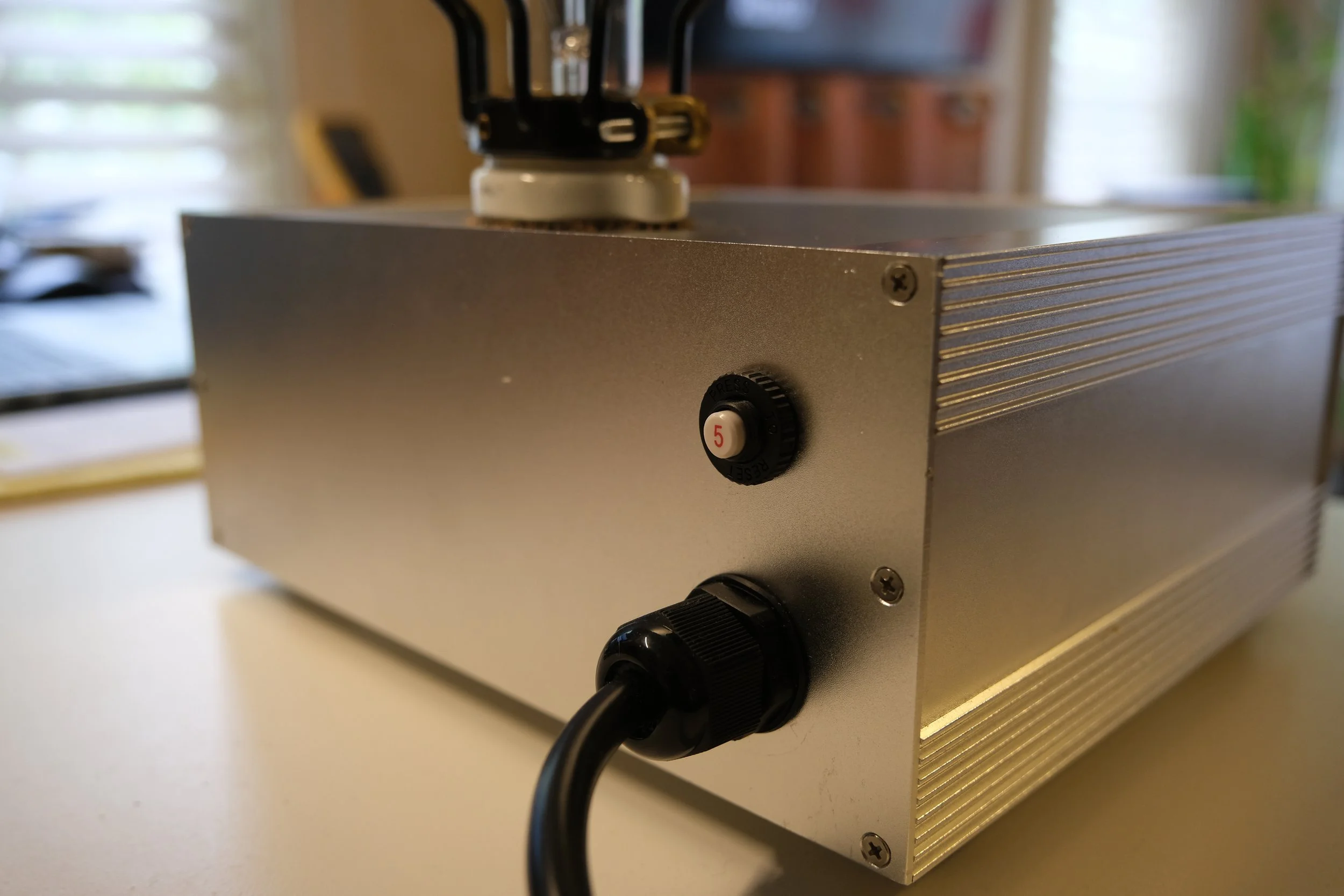
5A/250VAC Circuit Breaker — TE Connectivity PN: W57-XB1A7A10-5
Medium Base White Porcelain Socket — Leviton PN: L9878
MIL SPEC A-A-52080-B-3 Wax String
Some folks like zip ties, I’ve always preferred wax string; easy to manipulate, install, and remove.
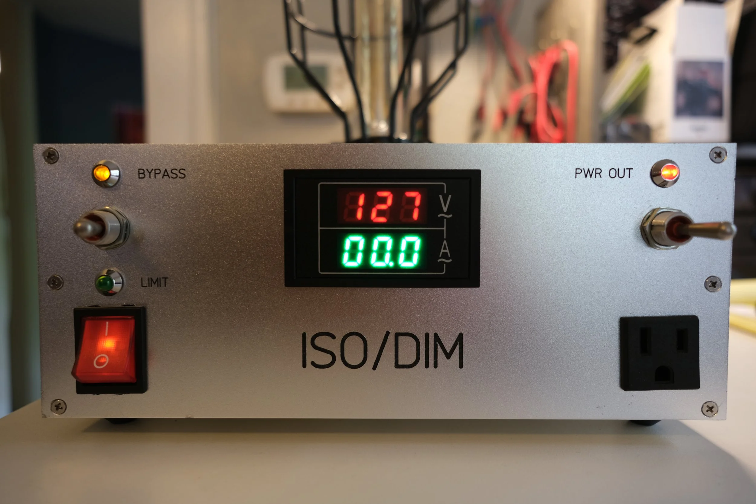
ISO/DIM, Power Off
Toroid Transformer
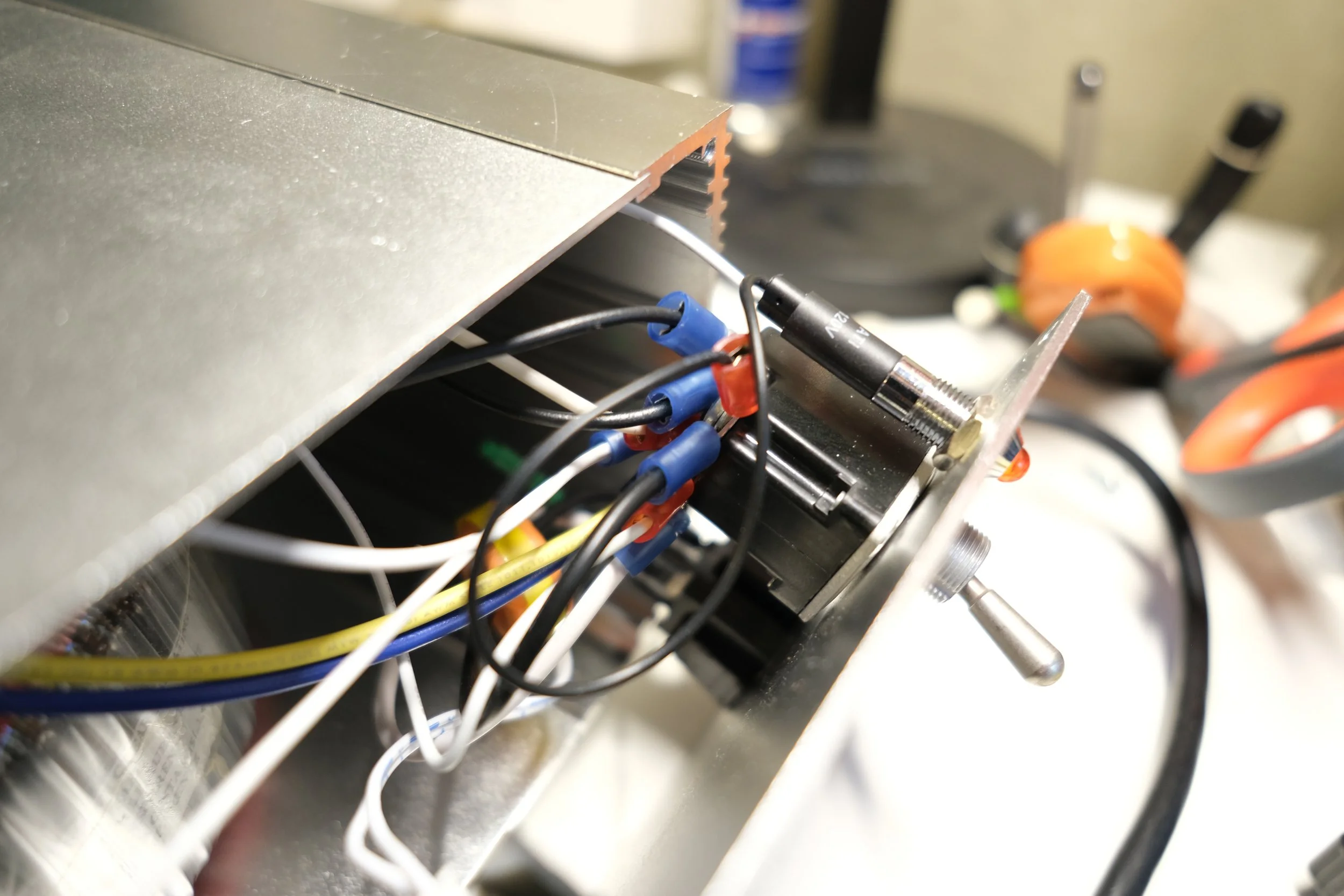
Input Section
Output Section
Rear Panel
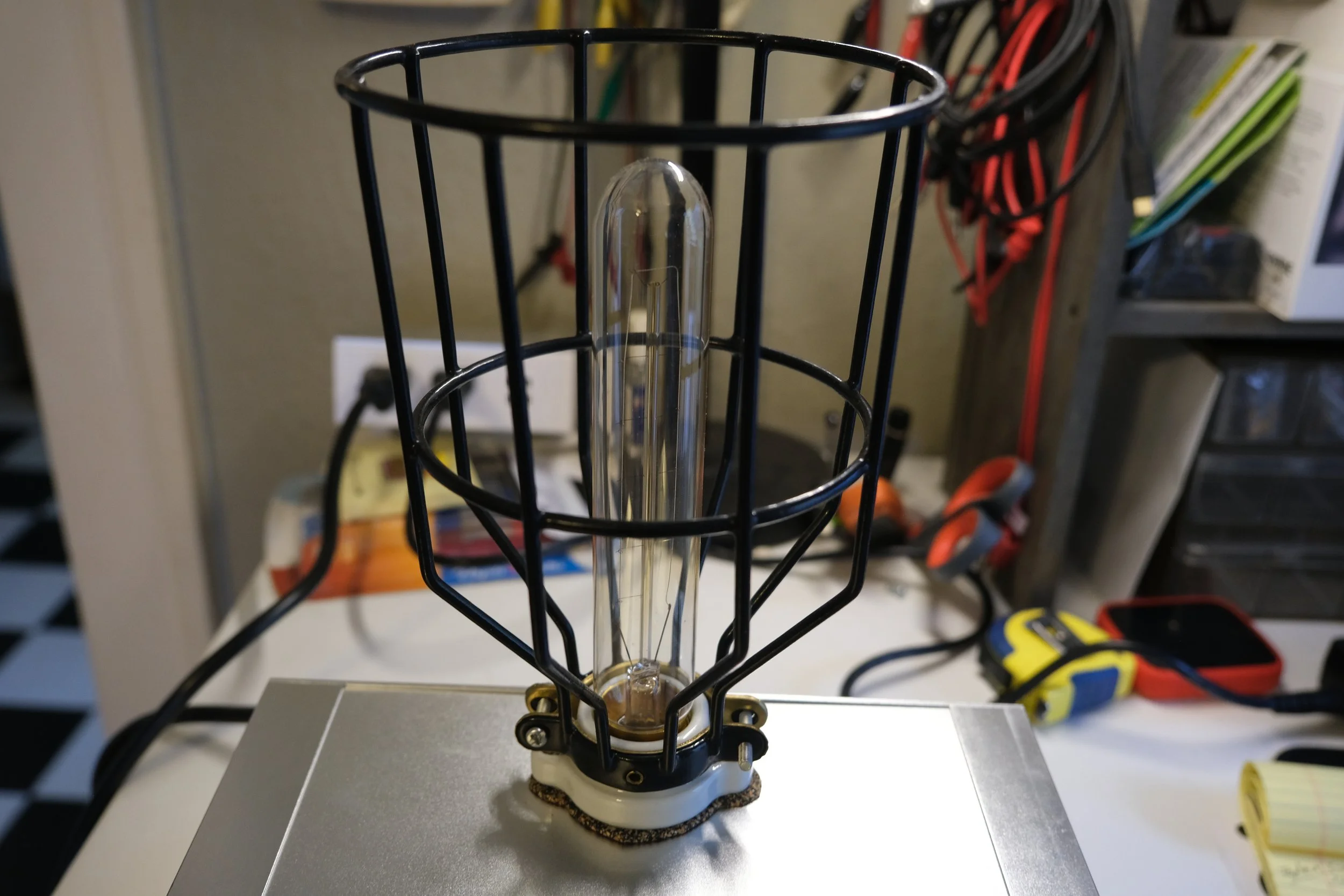
Socket, Bulb, & Cage
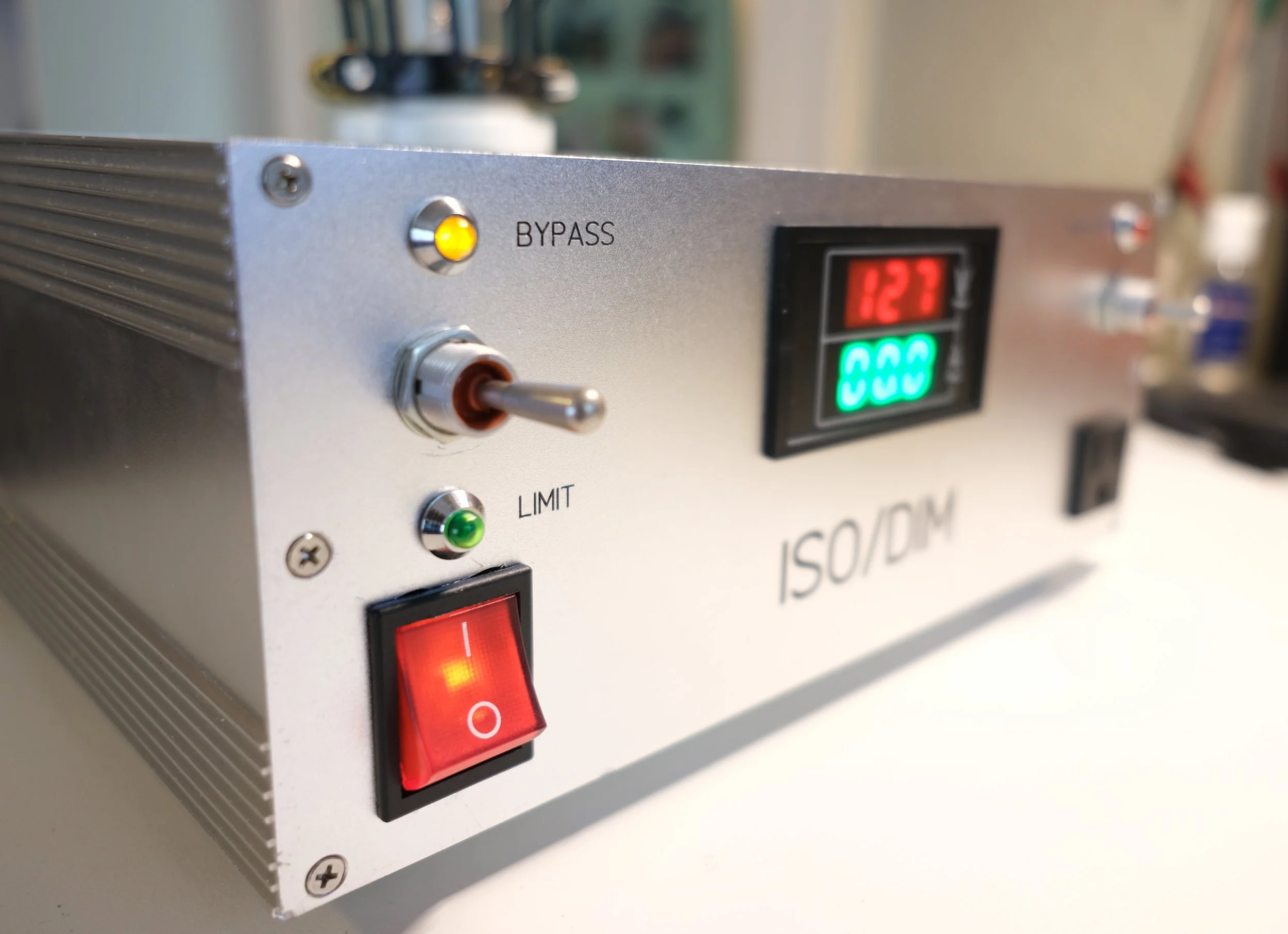
Front Panel, Input Section
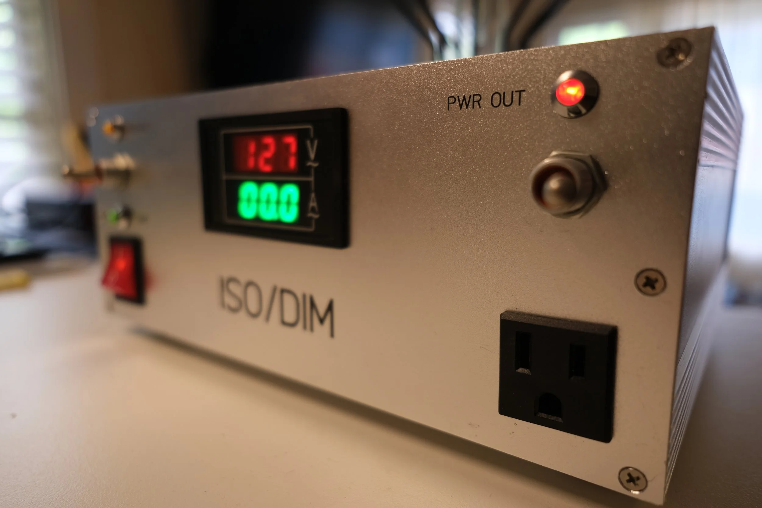
Front Panel, Output Section
ISO/DIM, Power On
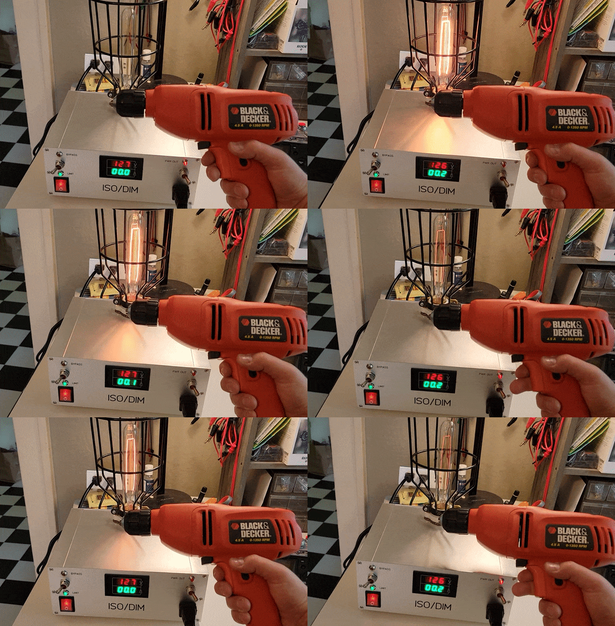
ISO/DIM - Limit
In this video the Limit/Bypass switch is set to limit. The 30W bulb limits the current draw of the drill to 0.25A, so little current that the drill cannot spin.
(You’ll notice the PWR OUT LED dims as the drill is engaged. This is not by design but since this does not affect operation I left well enough alone).
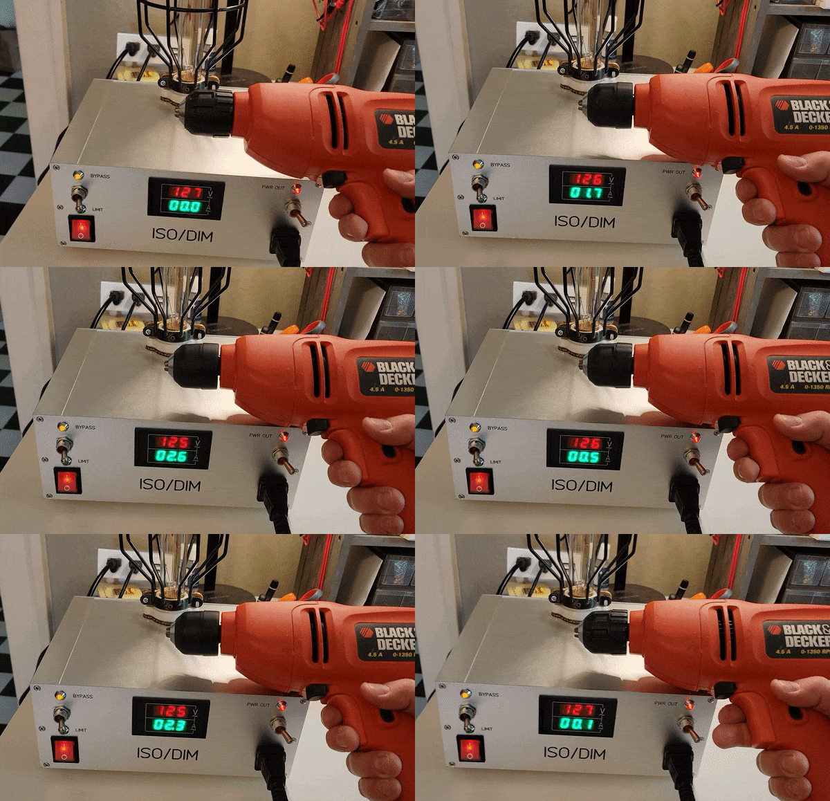
ISO/DIM - Bypass
In this video the Limit/Bypass switch is set to bypass. The 30W bulb is no longer in the circuit and the drill can draw all the current it requires to spin.
Mistakes & Lessons Learned
This was my first front panel design and while the software was straightforward to use, there’s the matter of tolerances. All installed units have a tolerance on their dimensions and in my mind if I was going to error, I should error on the side of making the cutouts too small (I can’t make the cutouts smaller if I go too large!). This was the right call but in a few instances I went much smaller than required and had to open up some of the cutouts by hand with a Dremel. This was a less than precise operation but fortunately the unit bezels cover the cutouts, mostly.
I cracked a porcelain socket while securing it to the chassis. One of those things you can see happen before it happens, but I kept tightening anyway.
The porcelain socket is held in place with two bolts. While moving the unit around I quickly noticed the socket, bulb, and cage wobbled quite a bit. So much so, in fact, that during a ride in the car the nuts on the inside nearly backed all the way off. The solution was to buy a thin sheet of cork and install it in between the porcelain socket and the chassis top panel. This inexpensive solution worked extremely well, securing the socket assembly tight to the top panel, with practically no wobble remaining at all.
The lever action of both the Limit/Bypass and Output Power switches were supposed to be vertical, not horizontal, to correspond to the labels above and below the switches. I originally ordered SPDT switches and designed the front panel based on the dimensions of those. The bodies of the DPDT switches are, unsurprisingly, larger than those of the SPDT switches. I could have redesigned (and paid for) another front panel or simply turned the switches sideways, and I did the latter.
The meter I went with was not my first choice. I wanted a unit that also displayed frequency and power, but they were all too deep and interfered with the very large toroidal transformer mounted dead center in the chassis. I could have moved the meter to either side of front panel to give its back end more room, but I preferred it stay in the center, with the input section on the left and the output section on the right, which felt to me a natural layout for a control panel.
Conclusion
This was a challenging project. It took longer and cost more than I had anticipated. While the electrical design is not particularly complicated, I had (have) very little experience in mechanical design — I had never even used calipers! Fortunately, I have access to a metal shop through my work, and the guys there helped out tremendously with drilling and cutting the chassis metal. I had neither the experience nor the tooling to do that on my own. Overall, I am very pleased with the end result.


