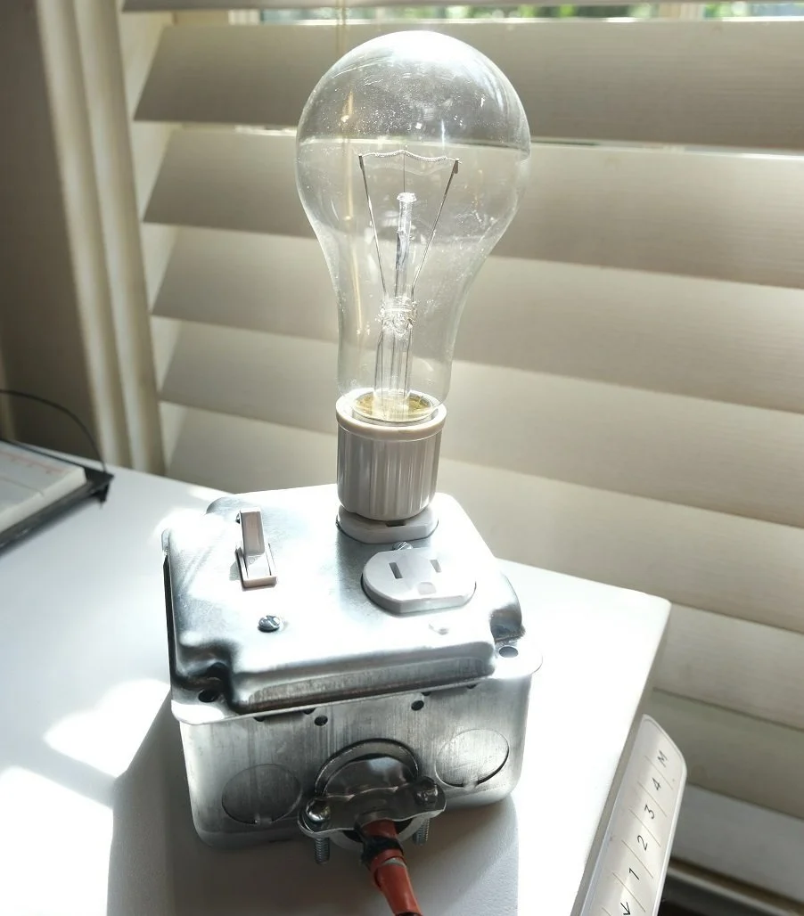
Dim Bulb Tester
Dim Bulb Tester
A dim bulb tester is a piece of test equipment used to protect your device under test (DUT) while providing a visual indication the DUT has a dead-short within it. The bulb acts as a load in series with your DUT, limiting the current to it.
Their primary use case is for the initial power up of tube amplifiers and receivers, which generally have at least one and sometimes several high voltage circuits inside of them. Additionally, as many of these units are now decades old, the electrolytic capacitors inside of them inevitably leak and fail creating short, open, and other potential electronic hazards. Limiting the current to these units upon power up ensures no damage to other components inside of these units, to your mains wiring, and most importantly, to yourself.
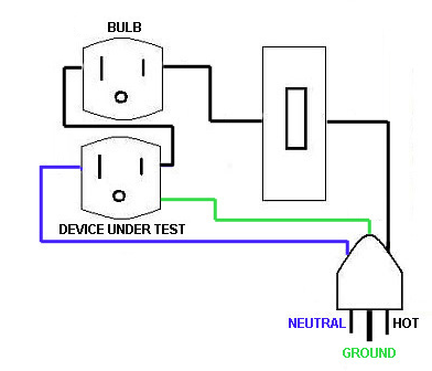
Dim Bulb Tester Wiring (source)
In the diagram above, the current-limiting lightbulb is plugged into the top outlet, while the DUT is plugged into the bottom outlet. The switch could be removed entirely from this design, though its inclusion represents a small effort (and cost) that provides an extra measure of control, making the device safer to use.
The amount of current available to the DUT is a function of the wattage of the bulb in series with it. P = IV, where P is power in watts, I is current in amps, and V is voltage in volts. The higher the wattage of bulb, the more current your DUT will see. For example,
200W = I(120V)
I = 1.67A
120W = I(120V)
I = 1A
30W = I(120V)
I = 0.25A
The illumination behavior of the lightbulb depends on a few factors. First is the current draw of your DUT. Assuming normal operation (no dead shorts), the lightbulb may briefly illuminate upon DUT power on — this corresponds to the initial in-rush or surge current associated with powering on the DUT. It may then extinguish as the DUT arrives at a steady state.
If, however, your DUT contains a dead short, the lightbulb will illuminate to full brightness and remain that way until power is removed. Remove power, disconnect your DUT, and being the process of troubleshooting.
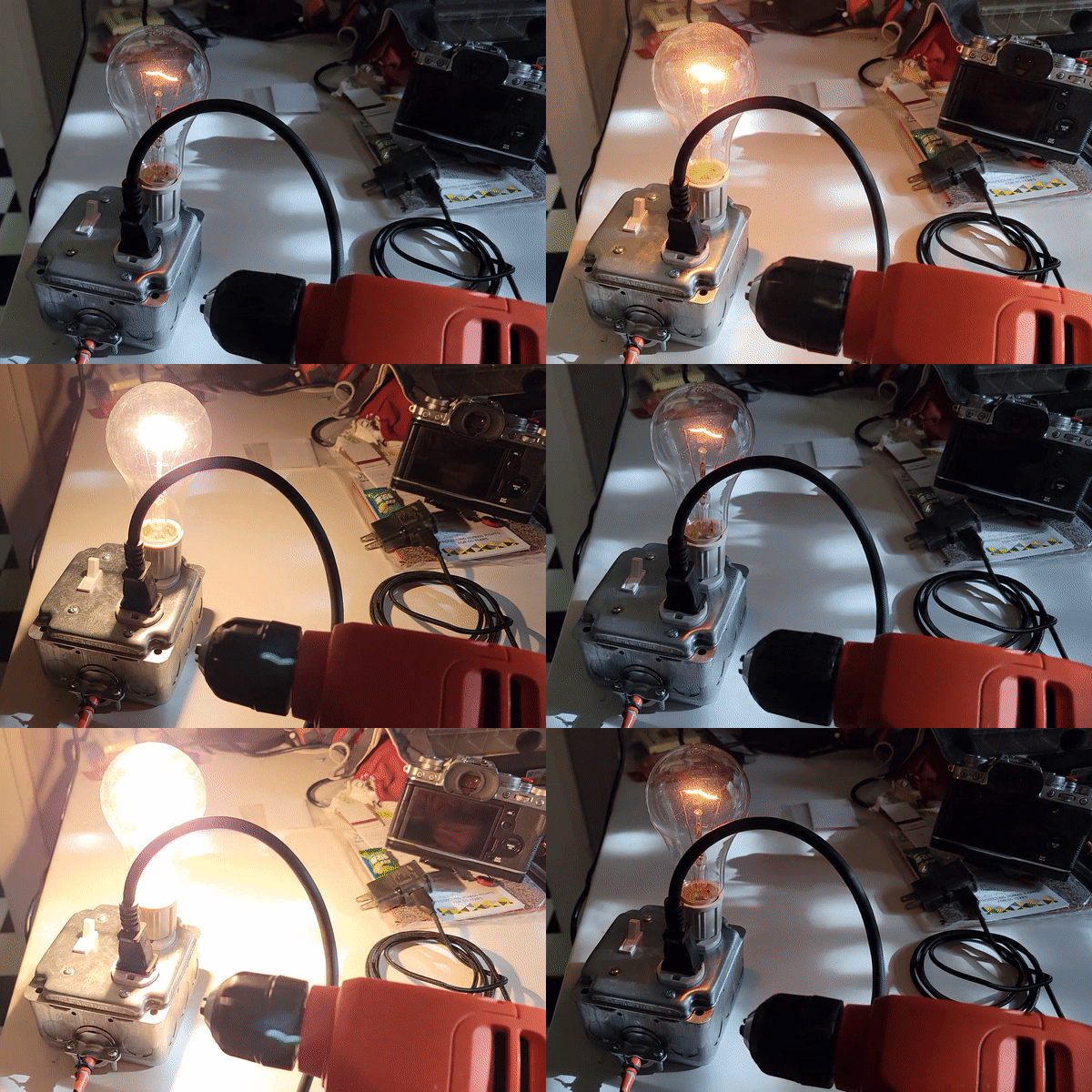
Dim Bulb Drill
In this video a drill is powered via the dim bulb tester. The drill draws a nominal 4.5A, but the 200W lightbulb limits the current to the drill to approximately 1.67A, ergo the rotation speed of the drill is also limited.
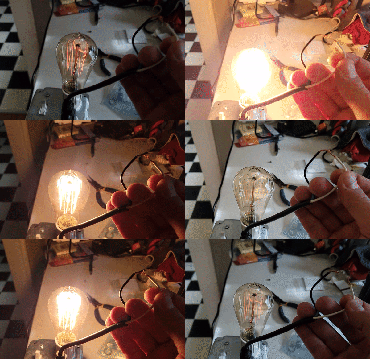
Dim Bulb Dead Short
In this video a 60W bulb is installed, limiting the current available to the DUT to 0.5A. The DUT in this case is a dead short created by touching the exposed hot and neutral wires of an extension cord together. The wires are shorted together, and the lightbulb fully illuminates.
DISCLAIMER: DO NOT TRY THIS AT HOME — SERIOUS INJURY, OR WORSE, CAN OCCUR
The simple dim bulb tester discussed above can be expanded upon and its functionality enhanced in many ways. Multiple bulbs could be wired in parallel and switched in as you see fit, allowing for the changing of the current limit on the fly. An isolation transformer can be added on the input side to further protect your DUT from your mains wiring, a highly recommended precaution when connecting an oscilloscope to troubleshoot. A variable isolation transformer (variac) can also be added on the input side to allow for the slow bringing up of the input voltage. People much smarter than I have dove deep into these topics, and I highly recommend their videos.
Electronics Old and New - Dim Bulb Limiter / Tester with Isolation
David Tipton - Variac Transformer / Dim Bulb Tester
Mr. Carlson's Lab - Big Dim Bulb Tester with Variac and Isolation Transformer
I enjoyed building this simple dim bulb tester, so I took it a step further and designed and built an Isolation Transformer / Dim Bulb Tester, which I call the ISO/DIM.


